The parts are:
- 60V motor, 5.0V I/O, 252kbyte flash A89211GEVSR
- 60V motor, 3.3V I/O, 128kbyte flash A89211GEVSR-A
- 90V motor, 5.0V I/O, 252kbyte flash A89212GEVSR
- 90V motor, 3.3V I/O, 128kbyte flash A89212GEVSR-A
- 90V motor, 5.0V I/O, 248kbyte flash A89224KEVSR-A
- 90V motor, 5.0V I/O, 128kbyte flash A89224KEVSR-B
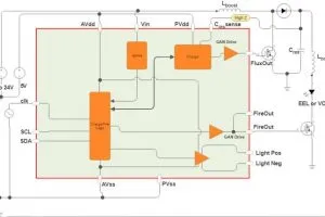
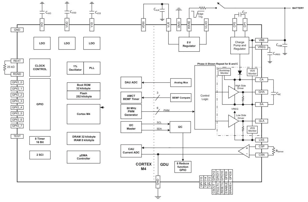
Each comes in a 7 x 7mm 48-pad QFN package with exposed thermal pad and wettable flanks, and is intended to drive six external n-channel power mosfets.
Specs are similar across the ICs with a 12bit 20kHz PWM, three 11bit 1µs ADCs for current measurement, a 12bit 1µs ADC with a 16channel multiplexer for other data acquisition, and eight GPIOs.
Communication is handled by a pair of serial busses.
Only the motor power supply is needed as internal logic voltages are derived from this by an on-die regulator. A charge pump is also included to provide above-rail drive for the high-side mosfets.
Regardless of 90 or 60V maximum supply, all operated down to 7V, or to 5.5V if reduced gate drive can be tolerated.
Allegro has not been shouting about theses ICs – only short-form data sheets are publicly available – but debug company Segger has outed them with the announcement that its J-Link debug probes and Flasher in-circuit programmers have been updated to handle Allegro’s implementation of the Cortex-M4 on these chips.
In April Allegro was on more familiar territory when it announced two current sensors and a motor driver without MCUs.