Arduinos plus ready-made modules are a very qick route to custom test gear, although this time the TM1637 based display module introduced a couple of spanners:
Find other CNC-related Engineer in Wonderland blogs here
Firstly, the ebay claim that it would be shipped from somewhere in the UK turned out to be false, and it took a day or two longer than the maximum estimated delivery time to arrive from the Far East – meanwhile the Pro Micro processor board arrived within in two days from a different supplier having indeed been shipped form the UK.
Secondly, at least two hours of precious time were wasted (and a lot of stress created) by what looked to be a problem up-loading code, but turned out to be a common fault on the display module.
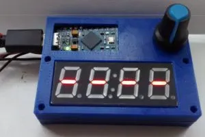
The Arduino in the photo (top) is a the clone Pro Micro – originally a board from Sparkfun, that squeezes most of an Arduino Leonardo onto a board a little smaller than Arduino’s own Micro.
The Pro Micro has an unusual ‘double-tap’ requirement when uploading code, which takes a little getting used to, plus there was the usual PC port confusion after a new install of the Arduino IDE, but, after much hair pulling, it turned out that code was uploading perfectly and was not the reason for random numbers flickering across the display.
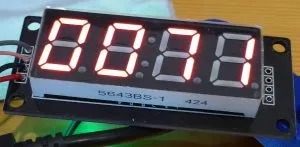
Instead, it transpired that this TM1637 module had huge (10nF) capacitors between 0V and the incoming clock and data, causing super-sluggish signal rise times (~100μs).
Credit for this discovery goes to a blog on Picprojects.org, where the author ‘Paul’ identified too-big capacitors as a source of his erratic TM1637 display behaviour.
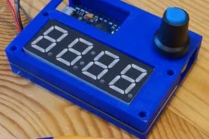
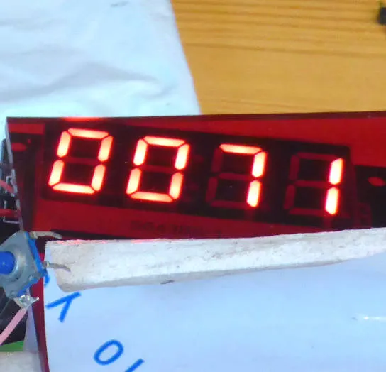 A red acrylic filter makes the display more readable
The TM1637 data sheet (Titan Micro Electronics) recommends 10k pull-ups and 100pF to ground for clock and data, and this module had 10k and 10nF.
The same IC data sheet recommends 10nF in parallel with 100μF across the 5V rail, and I wonder if some module maker in the past got confused, and other module makers simply copied the mistake – which seems to be wide-spread as the same google session revealed other folk resort to external low value (<1k) pull-ups to get their modules working.
Once the 10nF capacitors were removed, the thing instantly sprang into reliable operation (they are tiny caps, so refilling the footprints with 100pF types comes under ‘too hard’ at the moment).
Since then, the software is coming along – with the usual missed semi-colons causing head-scratching – oh to have trained as a real software engineer….
The current drag is compilation errors of the cryptic form: ‘xyz was not declared in this scope’ – forums are peppered with old hands jumping on naive folk for not understanding these ‘helpful’ words….
Update:
An hour at lunchtime fixed a few bits – retyping a variable name (to the same as it was) fixed one ‘not declared in this scope’ !
Code now works as a simple rev-counter by simply counting pulses for 1.25s.
Hats off to ‘Pete’ for getting to the bottom of the unreliable TM1637 module issue, ‘Avishay Orpaz’ for writing the de-facto TM1637 display library, and ‘Tarantula3’ for writing clear library use examples on Instructables.
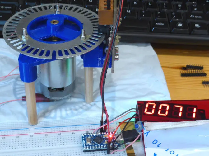
With the cnc lathe in pieces, the top photo shows a 3d printed motorised holder for the lathe’s encoder disc, with the Pro Micro and display alongside.
Scope measurements suggest that the perforated disc is not perfect and has 4% p-p jitter on both rising and falling edges.