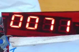
On a signal generator, the display is rock-solid and spot-on – the crystal on the Arduino Pro Micro clone is doing its job.
Find other CNC-related Engineer in Wonderland blogs here
Attached to the perforated 48 hole synchronisation wheel output there is jitter of maybe ±3 counts – not sure what else might be contributing, but there is certainly 4% perforation jitter, and a bit of wobble in the 3d printed temporary wheel mount.
Jitter is certainly not due to the original-equipment slotted opto-coupler, which is a very expensive type with an amplifier inside and few-nanosecond rise and fall times – somewhat over-kill for such a humble application, maybe, but that is what the lathe has.
With an eye to changing the way the lathe speed is controlled, a pwm generator has been added to the software, controlled by a potentiometer. Mediating this is a rudimentary safety feature which stops the motor jumping into life by inhibiting the pwm output at power-up until the control pot is turned all the way to its zero speed position (the machine will have a proper no-volt release as well).
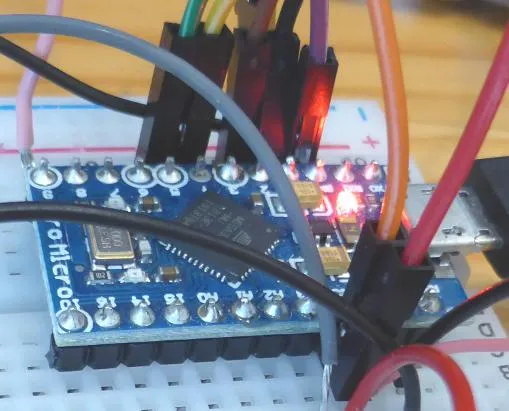 It was disappointing to discover that the Arduino function analogWriteResolution() does not seem to work with traditional AVR-based Arduinos like the Pro Micro (left) , so despite reading the pot to 10bits, the PWM is only set to 8bits – the analogWriteResolution() function page does not reveal this in its ‘Notes and Warnings’ section.
As ATmega 32U4 is perfectly capable of 10bit outputs from most of its pwm generators, time here must be found to write some custom code.
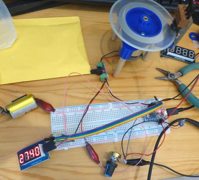
Via a mosfet (with hold-off resistor) and a back-emf Schottky, the pwm output has been temporarily fed into the test rig motor to vary its speed. BTW, the rig motor is powered by a discarded Li-ion vape battery – top photo.
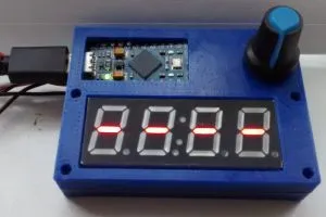
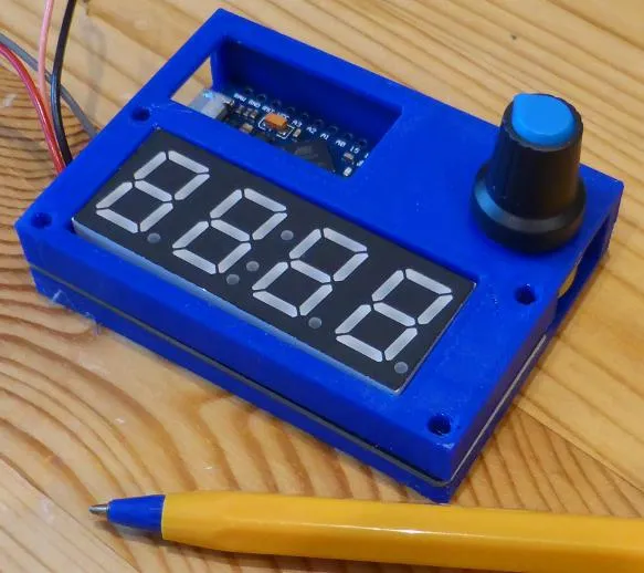 Housings have been designed and printed for a more rugged prototype that can be taken to the workshop (right).
If you want to use this code (without any guarantees at all), it is included below – remember that it will have picked up control characters from being published on a web site and will need cleaning up into a pure text file.
A note on TM1637 displays:
There are now two TM1637-based displays here, one has incorrect 10k/10nF clock and data input flters (scroll down) which stopped it working until the capacitors were removed, and the new smaller one has 10k/1nF filters which do work (but there might be sporadic display errors). The manufacturer recommends 10k/100pF.
The (not-guaranteed) code used so far (feel free to try it at your own risk):
// Rev counter for Denford Starturn Lathe
// or any rotating thing that makes multiple pulses per rev (set pulses/rev below)
// 15jun25 by Steve Bush, standing on the shoulders of Arduino giants 🙂
// To do – increase pwm resolution
// to do – sometimes a number briefly appears after
// the 8888 test if board has been reset instead of power-cycled
// Include the libraries
#include <TM1637Display.h>
// Define the connections pins
#define CLK 4
#define DIO 5
TM1637Display display(CLK, DIO); // Create an instance of the TM1637Display
const byte interruptPin = 2; // input pin that the interruption will be attached to
// Define constants and variables
volatile unsigned long Time; // variable that will be updated in the ISR
volatile unsigned long PulseCount; // variable that will be updated in the ISR
unsigned long LoopTime;
unsigned long LoopPulseCount;
unsigned long OldLoopTime;
unsigned long OldLoopPulseCount;
unsigned long Period;
unsigned long Pulses = 0;
float rpmLong;
float rpmFloat = 0;
float PulsesFloat;
float PeriodFloat;
float rpmconstant = 1250000.0; //60s in a min, times 1MHz ref freq, divided by 48 holes in the wheel
unsigned long previousMillis = 0; // will store last time display was updated
unsigned long currentMillis = millis();
const long interval = 333; // Time between display updates (milliseconds)
const unsigned int MaxStoppedDisplayCycles = 6; // number of display updates with no new pulses, so must have stopped
unsigned int StoppedDisplayCycleCount = 0; //counter for above
// Constants and vairables for Potentiometer and PWM routine
const byte PotInPin = A3;
const byte PwmoutPin = 9;
int PotVal;
unsigned long OldPwmMillis = 0; // will store last time display was updated
unsigned long PwmMillis = millis();
const long PwmInterval = 500; // Time between display updates (milliseconds)
bool PwmStartEnable = false; // prevents motor leaping intp life at switvh-on
void setup() {
display.setBrightness(5); // Set the display brightness (0-7)
pinMode(interruptPin, INPUT_PULLUP);
attachInterrupt(digitalPinToInterrupt(interruptPin), PulseReceived, FALLING);
display8s(); //turn on all used segments to test display
delay(500); // hold this for half a second
displayDashes(); // immediatley write dashes to show rev counter is idle
// Potentiometer and PWM routine
pinMode(PwmoutPin, OUTPUT); // set pwm pin to an output
};
void loop() {
// Is it time to do a calculation and display cycle
// unsigned long currentMillis = millis();
currentMillis = millis();
if (currentMillis – previousMillis >= interval) {
previousMillis = currentMillis; // save the last time display updated
// If it is time, get the necessary information stored by the interrupt routine
noInterrupts();
LoopPulseCount = PulseCount; // buffer information in interrupt routing
LoopTime = Time;
interrupts();
Pulses = LoopPulseCount – OldLoopPulseCount;
if (Pulses > 0) { //jump to end if no pulse occured in display period (for slow speeds)
OldLoopPulseCount = LoopPulseCount;
Period = LoopTime – OldLoopTime;
OldLoopTime = LoopTime;
// THIS IS THE REQUIRED MATHS
//Frequency=(Pulses*1000000)/Period
// now allow for RPM and number of holes in shutter RPM=(Frequency*60)/48
// values have to be converterd to floating point due to huge numbers
PulsesFloat = (float)Pulses;
PeriodFloat = (float)Period;
rpmFloat = (PulsesFloat * rpmconstant) / PeriodFloat;
int rpm = rpmFloat + 0.5; //round off rpmFloat and convert to integer
if (rpm > 9999) {
rpm = 9999;
}
display.clear(); // Clear the display
display.showNumberDec(rpm); // display the new speed
StoppedDisplayCycleCount = 0;
} else { // count pulse-free display cycles and eventually set display to dashes
StoppedDisplayCycleCount = StoppedDisplayCycleCount + 1;
if (StoppedDisplayCycleCount == MaxStoppedDisplayCycles) {
StoppedDisplayCycleCount = 0;
displayDashes();
}
}
}
// Potentiometer read and PWM output routine
PwmMillis = millis();
if (PwmMillis – OldPwmMillis >= PwmInterval) {
OldPwmMillis = PwmMillis; // save the last time PWM was updated
PotVal = analogRead(PotInPin); // read the input pin
if (PotVal == 0) {
PwmStartEnable = true;
}
if (PwmStartEnable == true) {
//analogWriteResolution(10); // increase pWM reolution from 8 to 10bit
//write that value to the PWM output pin
analogWrite(PwmoutPin, PotVal >> 2); // REMOVE >>2 (PotVal/4) when resolution = 10bit
}
}
}
// Interrupt service routine
void PulseReceived() {
Time = micros();
PulseCount = PulseCount + 1;
}
// Set the display to 8888 to test digits
void display8s() {
display.clear(); // Clear the display
uint8_t data[] = {
0x7F, 0x7F, 0x7F, 0x7F // put a 8 in each digit
};
display.setSegments(data); // Display the data
}
// Set the display to —- to indicate no movement
void displayDashes() {
display.clear(); // Clear the display
uint8_t data[] = {
SEG_G, // put a dash in each digit
SEG_G, //
SEG_G, //
SEG_G //
};
display.setSegments(data); // Display the data
}