

The brushless fan, from Pi Hut, is always on and, while it is commendably quiet, could be even quieter – especially as Raspberry Pi OS now includes an on-off control option that depends on CPU temperature.
See part 2 of taming a Raspberry Pi fan here
Find the option at: Raspberry-logo-menu – Preferences – Raspberry Pi Configuration – Performance
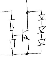
This toggles a (nominated) GPIO pin – there is no PWM – just 5V for ‘on’ and 0V for ‘off’. The GPIO pin itself will not power a fan on its own (my fan is labelled ‘0.2A’ and actually draws just under 100mA).
BTW, as far as I can see, this output is compatible with the PWM input of a controllable 5V fan, turning it on and off appropriately.
 One npn transistor and a couple of resistors is all that is needed to control the existing fan from the GPIO (left).
I recommend a ZTXxxx matrix-style npn transistor from Diodes (ex Zetex) for its low saturation voltage at low base current (and one being in my bits box), but almost any npn will control 100mA.
A ‘logic-level’ mosfet would also do it (also left), and in both the npn and the mosfet cases, the hold-off resistor could be left off (if you are a monster…).
There does not appear to be any need for a fly-back protection diode to the positive rail, as the fan seems to take care of this internally – this might not be the case for a brushed fan, or even all brushless fans.
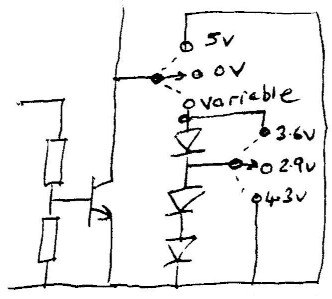
 To add a little more sophistication, one, two or three diodes can be added in series (right) to run the fan continuously at a slower speed before it is boosted to full (all cased Raspberry Pi 4s seem to need some sort of steady cooling if they are not to self-throttle). The resulting fan voltages measure ~4.3, 3.6 or 2.9V respectively, and the fan current is approx half the 5V current at 2.9V – so under 1/3 the power.
 Prototype Pi fan idle controller – the Pi-idle?
(pronounced pie-dle rathe than piddle, I feel…)
Yet-to-be-determined is which number of diodes is the ‘best’ compromise between sound level and CPU temperature at the Pi’s typical office-style workload, so the prototype is going to get a couple of single-pole double-throw centre-off switches for experimental purposes (left, voltages are across the fan) – allowing the idle state of the fan to be: ‘off’, 2.9V, 3.6V, 4.3V or ‘full-on’.
Physically, if no switching options are implemented, the whole circuit could be neatly birds-nested onto the fan wires inside the case – especially if the mosfet-with-no-resistor option is selected.
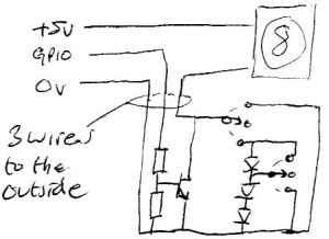 Or only three wires need to be led outside the case if a more bulky option is chosen (right).
For the switched option: note that the end terminals of the switches are wired in parallel, which eases soldering.


I always put two diodes in series with the fan on my Pi4s, and these keep the CPU temperature reporting at around 37 degC which seems civilised to me, though it would only marginally pass Bill Hewlett’s original edict that nothing must be more than 20deg above ambient in HP gear, except for tubes, crts, etc.
However some fans won’t start on the low voltage so I always put a 10uF in parallel with the diodes to give the fan a kick start.
Afternoon Mike
Nice to hear of someone else using diodes.
BTW, I did try up to three diode, and this fan started perfectly every time – nice little unit, although not full of fluff yet.
I like the idea of putting a capacitor across them, I hadn’t thought of that.
The added switches come from my motto of: Make it adjustable once, or….
Yes it’s the year or two’s accumulation of fluff that always gets you in the end 🙂
While I don’t own/use a Pi, I do love an excuse for a little analog tinkering. 🙂 The use of diodes to provide an alternate path to ground while the transistor is off is a clever idea! I imagine that a resistor would work too? As I ponder the opportunities to tinker, I can picture using a thermistor to source some current into the transistor’s base, and possibly provide a proportional control. The downside is the need to mount the thermistor near the processor’s heatsink, and the fiddling around to find a thermistor with the right resistance and suitable slope. I suppose a diode would be need to be placed in series with the Pi’s output pin, to keep it from sinking the current from the thermistor. Probably best just to keep things simple, as was proposed. 🙂
Afternoon Mr Kurt
Nice to hear from you.
Do get a Pi (after getting an Arduino if you are a lover of embedded electronics) – although they are quite hard to get due to chip shortages at the moment.
The thermistor in the transistor base sounds an nice idea, but too much development time for me – the person who has not even made the circuit above yet (note-to-self – must order those switches). Two transistors in parallel – one for the GPIO and one for the thermistor would save having a GPIO series diode and the turn-of problem that might add.
As for resistors controlling the fan, I think for a given final speed, they compromise start-up more than diodes do.