PFC is a technique employed in mains power supplies to prevent them injecting harmonic distortion into the mains (see box below).
However, “the switching loss in a PFC circuit adversely affects efficiency”, said TDK, which has focused on a particular part of the mains waveform with its patent.
“Most of the power in a sinewave is delivered away from the zero crossings,” TDK-Lambda CTO Andrew Skinner told Electronics Weekly. “Near the zero crossings the voltage is low, as is the current, giving low instantaneous power, but the power semiconductors are still switching between 0V and 380V [see below], creating more losses than the power drawn from the mains.”
At full load, TDK can still operate its PFC stage in the traditional way: throughout the mains cycle: through 360°/cycle (180°/half-cycle).
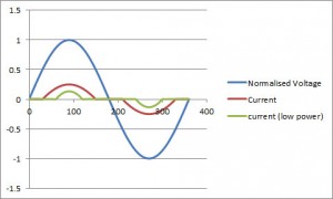
At partial load however, it has realised efficiency gains can be made without significantly contributing to mains harmonic distortion or contravening legal limits by completely turning off the PFC power semiconductors around the zero-crossing – see diagram.
“Typically, at input power below a few hundred watts, the phase angle is set for optimum efficiency. Above this, the phase angle may need to be widened to lower the harmonic content in order to meet the mains harmonic requirements,” said Skinner. “The conduction phase angle can be set anywhere from around 60° to 180°/half-cycle.
 One way to regulate a PFC stage is to use a negative feedback loop in which input current is made to follow a reference proportional to the instantaneous input voltage waveform – via a potentiometer for example.
In its scheme, rather than turn the PFC stage sharply on and off, it subtracts a fixed dc voltage from the input-proportional reference voltage. With this arrangement, the PFC comes smoothly into operation part-way through the cycle – (see graph, relative amplitudes are arbitrary).
“The reference in our implementation has a shape that is also derived from the input voltage waveform but instead of simply scaling the rectified ac voltage, it is first level-shifted,” said Skinner. “If no level-shifting is applied, we have achieved normal continuous-mode PFC waveforms, but if we subtract a constant voltage from the rectified mains, then the waveform looks like the graph. This smooth waveform has low harmonic content at high frequencies which reduces audible noise compared to a chopped sinewave.”
While the modified loop could be implemented by analogue control, TDK applies its load-dependent offset in the digital domain using a DSP.
“The control loop of the circuit is average current-mode control and identical to any other continuous-mode implementation with the exception that switching is stopped near the zero crossings where the reference current is also zero,” added Skinner.
Control laws within the DSP can be changed depending on the level of harmonic compliance required – for example LED lighting and computer equipment have more stringent limits.
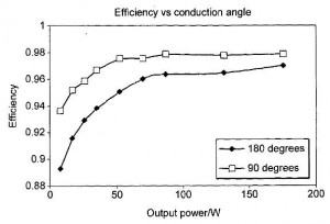
The second graph shows the effect of varying conduction angle on the efficiency of a prototype 600W PFC.
Power factor correction (PFC) in a nut shellPower factor is a mains power measure which essentially describes how far a load deviates from purely resistive behaviour – if supplied voltage and drawn current are entirely in-phase, the load is resistive and power factor is 1. Electronic loads tend to have mains rectifier and large front-end capacitor, which result in a non-unity power factor. Too many non-unity power factor loads, and the mains network starts to suffer. For the health of the national power grids, across the world mains PSUs drawing more than a defined power are required to control their own power factor. In Europe, standard EN 61000-3-2 defines the limits. “Although power supplies that operate up to 100W can comply with the limits with a power factor of around 0.6, at higher power levels a number close to unity is required,” said TDK Lambda. One way for electronic loads to comply is for their ac-dc converter to have ‘power factor correction’ between the input rectifier and front-end reservoir capacitor. Commonly a boost converter (boosting the input up to, typically, 380V on the reservoir capacitor), the PFC stage measures input voltage and current, and uses a feedback loop to keep input current in-phase with input voltage throughout the mains cycle. “Shaping the input current to be nearly sinusoidal is a common method to achieve compliance,” said Lambda. This is a successful strategy, and power factors around 0.99 are typically achieved – to the outside world, the load looks almost exactly like a resistor. Because input current is closely following input voltage, power draw also follows the input voltage (more accurately, the square of the input voltage), which means current delivered to the nominally 380V reservoir pulsates in sympathy with the mains voltage – which is why there has to be a reservoir capacitor to hold enough energy through the cycle for the following dc-dc stage to always deliver enough power to the final load. |
 Electronics Weekly
