 Aircraft control and auxiliary functions have always incorporated a mix of technologies, but these safety-critical technologies have been slow to update over the years. There is still a mix of oil hydraulics, compressed air, mechanical cables and electrics, but there has been a movement towards ‘more electric aircraft’ (MEA) since at least the 1990s. The EU’s Clean Aviation programme and the US Federal Aviation Administration are investing in MEA, in line with the International Air Transport Association’s pledge to achieve carbon neutrality by 2050.
MEA aims to improve reliability and reduce equipment cost, weight, maintenance and fuel consumption. Around 6% of engine power is diverted for control and other functions such as cabin climate air conditioning. The electrical power comes from a generator attached to a gearbox in the engine, producing typically 270Vdc nominal, which is then down-converted to 28Vdc for use as power to actuators and pumps, and dropped further to operating voltages for electronics. The power conversion equipment, however, must be small, lightweight and efficient to achieve the desired gains.
LLC converters
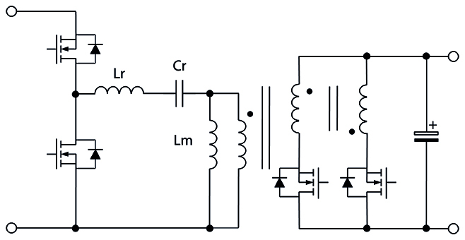
Three-phase LLC converters are candidates for efficiency and power density gains. Conversion from 270-28Vdc requires isolation. A popular choice of power converter topology might be the LLC type (Figure 1), which transfers power resonantly through two inductors, Lr and Lm, and a capacitor Cr. Lm is the magnetising inductance of a transformer with output power taken from its secondary.
Regulation is achieved by varying the frequency of excitation of the resonant circuit up and down the ‘side slope’ of the resonance curve, representing an increasing or decreasing gain of the network, which can help control the output voltage through feedback. One of the attractions of the topology is that Lr can often be integrated into the transformer as deliberate leakage inductance, simplifying the circuit while reducing cost and weight.
Although the circuit has low dynamic losses, the variable frequency can be problematic in MEA applications, which can stipulate a maximum variation from nominal to meet EMC rules, typically ±15%. This can be achieved with the LLC, but Lr gets larger as the frequency range reduces, and in practice, for this application, it must be a discrete component, losing some LLC cost and size advantages.
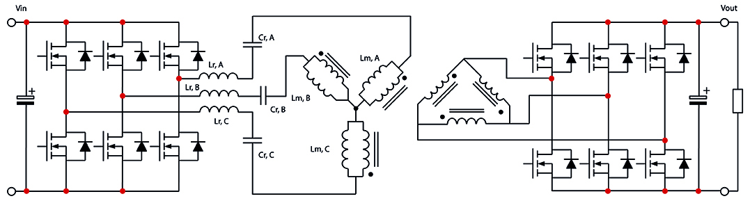 Perhaps counter-intuitively, implementing a more complex three-phase version of the topology (Figure 2) can be a net advantage to claw back power density and improve efficiency. More switches are used, but the total area of silicon is less, as lower current is spread across multiple smaller devices, which then see more than proportionate reduction in losses because of the ‘square’ term in ‘I2Ron’ (Figure 3).
 Input and output ripple currents are substantially reduced, allowing much smaller capacitors. Although three separate resonant inductors are needed, they are each smaller than the inductor in a single-phase LLC. The transformer sees partial current cancellation and can be about 40% smaller, with 60% lower losses than a single-phase LLC version. There are more gate drives involved, but these are simple 50% duty cycle pulse trains and are, therefore, easy to implement.
Analysis in the time domain
The LLC converter is notoriously difficult to model accurately. Researchers at the Universidad Politecnica de Madrid and GAIA Converter have investigated alternative methods to evaluate both the single- and three-phase LLC in an MEA application. Analysis has started with a first harmonic approximation (FHA), which assumes that only the fundamental resonance contributes to an energy transfer from primary to secondary, ignoring harmonics in the waveform. The analysis then plots the gain of the resonant circuit with frequency to determine the frequency deviation required for regulation.
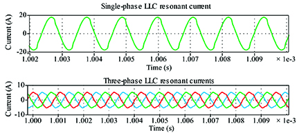
Given the sensitivity of the MEA application to this parameter, the result is not accurate enough, so a traditional time domain analysis was considered. This analysis requires a complete understanding of static and dynamic values for the circuit’s R, C, and L elements and boundary values for voltages and currents in all operating phases of a switching cycle. The method is computationally intensive, but should yield the best accuracy. The analysis results are shown in Figure 4, with the time domain method compared with a Plecs simulation, which is in agreement, and the FHA approach shows up to around 5% deviation.
Optimising for SWaP
Using the now-validated time domain analysis, the research team compared actual results from a SWaP (size, weight and power) -optimised single-phase LLC converter with a simulated three-phase version. The specification was 1kW output at 28Vdc, an input ranging from 235-285Vdc, and a maximum allowed frequency deviation of ±15% over load variation down to 600W. Minimum efficiency was 96%, and product height was 13mm maximum.
A matrix transformer was used in the single-phase LLC, while a gapped planar type was used in the three-phase converter, along with three separate resonant inductors. GaN HEMT cells were used as primary switches in both converters, and secondary switches were silicon mosfets.
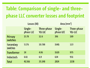 The table shows the results achieved, with overall losses reduced by 15% and power density improved by 20% using the three-phase LLC. In addition, output ripple voltage in the three-phase version was reduced by a factor of 100 for the same capacitance value.
The three-phase LLC could be a strong contender for improving critical performance parameters in MEA applications. At the same time, the validation of the time domain analysis of operation for an LLC converter shows that designs can be simulated and prototyped with confidence in a working product.