Vehicle electrical systems have grown increasingly complex, with increasing numbers of ECUs
The evolution of vehicle architectures, driven by advances in electric vehicles (EVs), hybrid electric vehicles and increased demand for ADAS (advanced driver-assistance systems) features, has brought about some significant changes in the way electronic systems are designed and managed. The modern vehicle’s electrical system has become more complex, requiring smarter, more efficient ways to manage power distribution.
Advances mean complexity
As vehicles become more electrified and connected, the demands on vehicle electrical systems have increased dramatically. The number of electronic control units (ECUs) in vehicles has surged and resulted in more complex vehicle networks. In modern cars the number of ECUs can now exceed 100 units, compared to around 20 to 30 in traditional vehicles made a decade ago (source IEEE Spectrum). This increase is partly due to the growing integration of ADAS features, which require real-time fusion processing of data from multiple sensor classes.
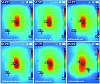
Figure 1: The high-side switch’s nominal current rating is key for managing internal impedance and heat dissipation, especially for resistive loads, for example, seat heaters, as shown in this infrared image
The evolution from body control modules (BCMs) to zonal control units (ZCUs) reflects the growing shift towards decentralisation in vehicle electronics. BCMs centralise the management of vehicle body functions such as lighting, while ZCUs streamline wiring by managing localised functions within specific vehicle zones. This decentralised approach not only makes it easier to update software but also supports ADAS and the growing requirements of modern EV systems.
Load types
The shift to ZCUs creates several new headaches for designers, such as increased software complexity, maintaining fault tolerance and managing the power needs of various loads across multiple decentralised systems.
High-side switches help solve these issues by providing efficient and precise control over those loads while offering protection mechanisms to ensure reliability and safety. (See the Fact File section below.)
Typical applications include over-current/short-circuit protection, over-temperature protection, over-voltage protection, ground and power loss protection, reverse polarity protection and open-load detection.
To manage these loads, high-side switches should be pre-qualified for various automotive standards. For example, the NSE34/35 series is pre-qualified for AEC-Q100, AEC-Q100-006 and AEC-Q100-012 level A, with Rds(on) values from 8mΩ to 140mΩ. The resistance range allows performance to be optimised based on specific system requirements. For example, in high-current applications, such as heated seats, the low Rds(on) value of the NSE34012D (a dual-channel, 12mΩ high-side switch) ensures minimal heat generation to enhance system efficiency.
The series offers options for one, two, or four channels and is available in HSSOP-16 and HSSOP-14 packages
Protection features enable the high-side switch to handle large capacitive loads effectively. For example, the NSE35xxx family has over-current protection, which ensures that in-rush currents created when starting capacitive loads are managed without causing damage to the system.
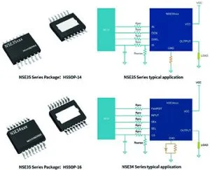
Figure 2 – The NSE34/35 series of high-side switches
Other designs can be designed for over-voltage clamping, for example, the NSE35008SA. This ensures the safe operation of inductive loads and prolongs the life of the vehicle’s electronic systems (windscreen wiper motors or relays).
For automotive systems, where many applications require continuous monitoring, a vital key performance indicator is the precision of the switch’s current sensing. This enables the early detection of potential failures and is essential for real-time diagnostics and fault detection.
The adaptability and robust protection features of high-side switches make them an indispensable component in managing vehicle architectures. They can drive the more traditional resistive, inductive and halogen lamp loads in BCMs as well as the large capacitive loads commonly found in the first-level and second-level power distribution of ZCU architectures.
FACT FILE
Switch operation examples
Here are three scenarios, illustrating the control and protection necessary in vehicle architectures.
Resistive loads
Resistive loads, such as heating and lighting systems, are common in automotive applications. The primary concern when driving resistive loads is managing heat dissipation due to the electrical resistance inherent in these components. High-side switches provide low on-resistance, reducing the heat generated as current flows through the system.
Capacitive loads
Capacitive loads, including many power distribution systems such as cold-starting halogen lamps, pose a different set of challenges. When capacitive loads are first energised they can draw large in-rush currents far above their normal operating levels. Without proper management these surges can cause instability or even damage to the electrical system. High-side switches handle these currents with features such as over-current protection, ensuring that the system remains stable and safe during power-up. These capabilities make them particularly useful in managing the power delivery of ZCUs.
Inductive loads
Inductive loads, such as solenoids, motors and relays, generate significant voltage spikes when they are deactivated due to the energy stored in the magnetic field of the inductive component, which can lead to damaging voltage spikes (or ‘back EMF’). High-side switches mitigate these spikes by incorporating clamping or suppression techniques that absorb excess energy, protecting the vehicle’s sensitive electronics. By ensuring that these voltage spikes are safely dissipated, high-side switches are suitable for vehicle electrical systems involving frequent switching of inductive components, for example, windscreen wiper motors and electric locks.