It is the DCM34xx01 series, and it has been designed to typically provide 100kV/μs common-mode transient immunity, in electric vehicle on-board chargers and battery management systems.
Depending on the exact part, there can be:
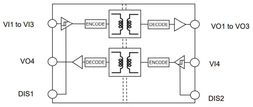
- Four forward channels
- Three forward and one reverse
- Two forward and two reverse
Separately, some have input-side disables, some have output-side disables, some outputs default to logic-high with no input, and some default to logic-low.
There are initially 10 devices, so not all possible combinations are available.
“They typically provide pulse-width distortion of just 0.8ns and are suitable for multi-channel high-speed communication applications, including non-automotive uses such as IO interfaces with SPI communications,” according to the company.
Both sides of the isolation barrier need a power supply between 3 and 5.5V, however, they are specified with equal voltages on the input and output at 3.3V or 5V.
Power consumption is different at different logic levels and at different clocking speeds – ‘low tens of mA’ would be an approximation – check the data sheets for detail.
The package, a 16pin wide-bodies SOIC, provides: 7.6mm creepage, 8mm clearance and 17µm through-isolation distance. Comparative tracking index is 550V, and the isolation barrier is rated to 5kV for one minute.
Operation is over -40 to +125°C (junction to 150°C), and they are qualified to AEC-Q100.
Picking one almost at random, the DCM341B01 data sheet can be found here.
Find some UL-approved 100Mbit/s digital isolators in this article