“Developed in accordance with ISO 26262, the TLE4960x switches integrate diagnostic functions to support functional safety applications,” according to Infineon. “In addition, the devices are AEC-Q100 compliant and qualified to Grade 0, ensuring robust performance in harsh environments.”
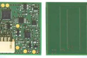
With the base part number TLE4960x-xM-S2, they come in a simple surface-mount SOT-23 package and measure a magnetic field orthogonal to the plane of the printed circuit board.
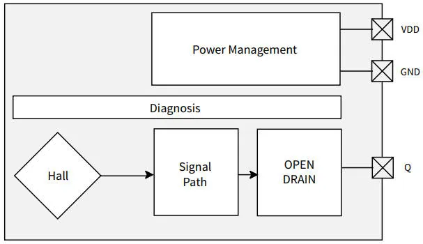
The three pins are power, ground and an open drain output which switches in various magnetic conditions depending on the part number – more of that later.
Protection is included for over-current and over-temperature, and faults outside the safe operating area are telegraphed to the following microcontroller using short pulses that Infineon calls ‘life ticks’ – see below where Infineon explains life ticks to Electronics Weekly.
In normal operation, the output switches on and off at two thresholds with hysteresis in between.
There are latching types with thresholds at ±2mT, ±7.5mT or ±15mT, then unipolar parts with thresholds at 18/12.5mT, 28/22.5mT, 10/8.5mT, 3.5/2.5mT or 9.5/7mT, and a bipolar part with ±1mT thresholds. See below for Infineon’s explanation of Electronics latching and bipolar types.
Operation is across 3 to 32V and -40 to +175°C, and up to 10kHz. Consumption is 1.6mA.
absolute maximum ratings stretch across -18 to +42V on the power supply pin.
Applications are foreseen in window regulators, sunroof actuators and seat adjusters.
Find an example Infineon web page here – for the ±1mT TLE49608-1M-S2
Infineon explains ‘life tick’ fault indication:
Fault indication is done only via the life tick which is issued as a ~10µs pulse every ~10ms.
If this pulse isn’t issued from the sensor, and the [sensed] magnetic frequency is below Fcorner [33 – 83Hz], the device can be considered as defective from the point of view of an external microcontroller.
The life tick will appear in any case up to 33Hz. Above 33Hz it depends on external conditions like Vdd and temperature. Above 83Hz, the life tick [always] gets deactivated. This means at magnetic frequencies higher than 83 Hz sensor faults need to be detected at the application level by its reaction and current consumption – which is usually easily achievable.
In order to be sure that the life tick is not misinterpreted as useful signal, you need to differentiate by, for example, by using a timer set to 16µs.
If the fault is already detected at start-up, no life tick will be issued and the sensor output will stay in the high state. When the senor doesn’t work at all, also no life tick will be issued, so a completely defective device is also covered by design of the life tick.
Infineon explains unipolar, latching and bipolar action:
Latches switch on when they see a magnetic south pole and switch off when they see a magnetic north pole higher than the devices thresholds – often used for pole wheels and motor commutation.
Unipolar switches switch on when the see a magnetic south pole of sufficient strength higher than the magnetic operating point (BOP) and switch off when the magnetic field gets weaker than the magnetic release point (BRP) – often used for position sensing, like for push buttons.
Bipolar switches are a combination of bipolar latches and unipolar switches. They switch on and of like latches but don’t latch their state, and their BOP – BRP hysteresis windows often overlap over temperature. [This means that] you can only trust switching edges, not the current state, [making] bipolar switches only for motor commutation or pole wheel counting. [However] very low thresholds, of only ±1mT, can be reached by this technology.
Melexis introduced a series of automotive magnetic angle sensors towards the end of last year